Ask an Engineer: 3D Printing Metal Parts
It’s no secret, designing for manufacturing can be a difficult undertaking. Product engineers need to consider several variables that range from material and process selection to managing costs and deadlines. The team of application engineers at China Metal Parts understand this, and helps product developers with these challenges every day.
Our Ask an Engineer series highlights some of the most common questions we receive regarding manufacturing. And if you have questions please don’t hesitate to email us at [email protected]. There’s a good chance we’ll feature your question in our next post.
What file format delivers the best result and least amount of deficiencies? Does file format matter?
In short, file type doesn’t really matter for our process. No matter what file format we receive from a customer, we have to build from an STL file for 3D printing. So if we receive a file type like SolidWorks (.sldprt), STEP (.stp), or IGES (.igs), we will convert it into an .stl file. One consideration to keep in mind when saving a file for 3D printing is resolution. Determining the optimal resolution will depend on your part’s geometry. If you have a question on the resolution of your file, our applications engineers will help you with this step.

With 3D plastic printing you can build hollow parts, does powder-based metal 3D printing have a similar capability?
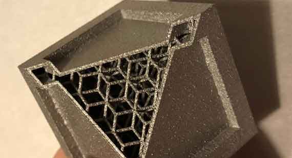
You can print hollow parts with direct metal laser sintering (DMLS) but you need to be mindful of powder removal. Since these parts are built in a bed of powder, any hollow features will need to have a hole that makes it possible to remove powder. Think of a hollow cube for example. You first build the base and as the four walls are built, layer by layer, they are forming around existing powder in the bed. Somewhere on the cube there will need to be a hole to empty excess powder once the build is complete.
Unlike fused deposition modeling (FDM), which has infill settings, there are no similar settings built into our DMLS software, so we will have to model it in. This additional design work is a more manual process but will achieve similar results.
What process controls does China Metal Parts have in place for DMLS?
With every build that we run, we have statistical process controlled (SPC) parts. Each time we build a customer’s part, we are monitoring characteristics like tensile properties and density. Further, we keep a database of all of those properties to monitor the output of each system regularly and this enables us to control our part quality. We do this for every part across all of our processes and it’s critical to 3D printing precision parts.
When manufacturing internal channels with DMLS, can you assume that these channels will be air- or watertight? Do they need to be coated to prevent leaks?
Yes, you can assume that DMLS will build air- and watertight parts without any coating since it’s a near-100 percent dense process. You can have random porosity that occurs due to porosity within the powder or random spots here and there, but as long as you don’t have interconnected porosity in your part, there should be no issues.

What considerations should be taken when choosing a heat treating process for stress reduction in 3D-printed parts?
Stress relief for metal 3D-printed parts is fairly straightforward. The parts will respond to heat treatment just like a wrought part would since the materials used in DMLS are produced from common alloys. For our post-build stress relief process, we work from the ASTM or AMS guidelines for the given material.
Note that in order to achieve the properties of the wrought material, additional stress relief processes may be required. Depending on the material, you may need to apply a solution heat treatment, precipitation hardening, or aging in addition to the standard heat treating process.
How do we determine build orientation?
Determining the optimal orientation of a design is part of our 3D printing service at China Metal Parts. Getting creative with part orientation can be the difference between a fully functional component and a failed build. When selecting how a part will be oriented, we have three goals in mind: achieve self-supporting angles, minimize the need for support structures, and reduce large changes in cross section in order to reduce warpage.
We hope you found this post helpful! Let us know what questions you have by sending us an email at [email protected] or tweeting us @Protolabs.