Molding Quality Parts with Automated Design Analysis
While quality assurance is often thought of as a combination of in-process inspections and controls and dimensional verification after production, designing a part with the manufacturing process in mind is the first step in ensuring a quality molded part. That’s why we provide design analysis with every injection molding quote. Getting design for manufacturability feedback early in the manufacturing process can help eliminate costly redesigns, save development time, and take the guess work out of the molding process.
Our software analyzes a 3D CAD model and identifies features that may present issues or be difficult to mold. Before placing an order, you’ll know if your design requires any changes, get recommendations to improve its moldability, and see other useful information to understand how the final part will be molded.
The design for manufacturability feedback is broken down into three categories: required changes, moldability advisory, and other info. Common moldability advisories that the design analysis highlights, include:
Undercuts. Since our process is designed for speed, we do not use collapsible cores or lifters like a traditional high-volume production house to mold parts with undercuts. Instead we can use a variety of pickout inserts and side-pulls to mold geometries with undercuts. If an undercut is identified in your required changes section of your quote, talk to an applications engineer to learn what your options are for your design. Review our injection molding design guidelines to see maximum side-core dimensions.
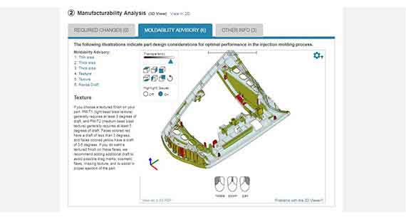
Draft. Having enough draft on your design will make sure the part ejects properly and can even impact the life of your mold. Our baseline requirement is 0.5 degrees of draft on vertical faces if possible, but at least 2 degrees of draft is recommended. If your part has zero draft, we can still attempt to mold the part but be aware that this may result in drag marks and could cause production delays if more issues arise. Another important consideration is that certain textures like bead blast finishes will require more draft. For example, we require 3 degrees on T1 finishes and 5 degrees for T2.
Internal Faces. Oftentimes CAD files can have artifacts after converting the original CAD to an IGES or STEP file. To prevent this, double check the converted CAD file before uploading to make sure all faces are clear of any small artifacts.
Text. Our design analysis will flag any text that our milling toolset is not able to produce. Our standard rule of thumb is to use raised text, and select bold sans-serif font that is equal to or greater than 20 points.
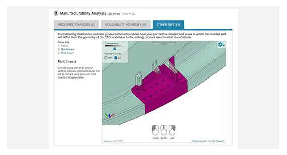
The Other Info Tab
The “Other Info” tab provides important information regarding radii, custom surface finishes, and inserts for undercuts.
Radius. The size of radius is dependent upon what type of tool we use to cut. Within this tab, you’ll see radii identified with assigned colors. This is important to review before placing an order as it can vary slightly from your original design. You’ll also be notified if your part has features that cannot be fully formed. Those are highlighted in dark red.
Mold Insert. The Other Info section also identifies features that will be molded with the use of either a pickout, mold inserts, or stripper plates. These are highlighted with a small chevron pattern. If cost is a concern, consider reworking the feature design so that it can be made without side-actions or pickouts.
More 3D Viewer Tips
If you’re having difficulty viewing a feature identified within your design analysis, select the advisory or required change and drag the transparency slider all the way to right. This will hide the rest of the design except for the feature that has been called out within the design analysis. Additionally, you can click the gear icon to quickly jump to orthogonal views of your design or switch between metric and imperial measurements.
Another important factor to be aware of is the pull direction of the mold. Look in the lower left hand corner of the 3D CAD viewer, you’ll see red, green, and blue lines. The blue arrow is the mold’s pull direction. The green and red lines indicates the side-action directions for any cams used to accommodate for undercuts. The blue side of the part indicates the B side of the mold and the green is the A side.
Finally, here are some hot keys that make your DFM analysis easier to use:
~ = orthogonal views
D = Dimensions (place mouse cursor on surface/location you want to start dimension measurement from and drag crosshair to surface/location you want to measure to)
F = Draft