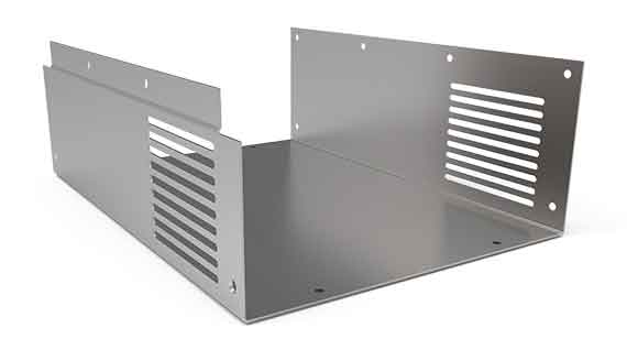
Design Guidelines: Sheet Metal Fabrication
Our basic guidelines for sheet metal fabrication include important design considerations to help improve part manufacturability, enhance cosmetic appearance, and reduce overall production time.
Size
Maximum Dimensions
| SIZE | 47 in. x 119 in. |
|---|---|
| BEND LENGTH | 10 ft. |
| SIZE | 1,193.8mm x 3,022.6mm |
|---|---|
| LENGTH | 3.048m |
Minimum Dimensions
| FLAT PART | 0.5 in. x 0.5 in. |
|---|---|
| FORMED PART | 1.5 in. x 1.5 in. |
| FLAT PART | 12.7mm x 12.7mm |
|---|---|
| FORMED PART | 38.1mm x 38.1mm |
Tolerances
Single Surface
| Bends | +/- 1 degree |
|---|---|
| Offsets | +/- 0.012 in. |
| Hole Diameters | +/- 0.005 in. |
| Edge to edge/hole; hole to hole | +/- 0.005 in. |
| Hardware to edge/hole | +/- 0.010 in. |
| Hardware to hardware | +/- 0.015 in. |
| Bend to edge | +/- 0.010 in. |
| Bend to hole/hardware/bend | +/- 0.015 in. |
| Bends | +/- 1 degree |
|---|---|
| Offsets | +/- 0.304mm |
| Hole Diameters | +/- 0.127mm |
| Edge to edge/hole; hole to hole | +/- 0.127mm |
| Hardware to edge/hole | +/- 0.254mm |
| Hardware to hardware | +/- 0.381mm |
| Bend to edge | +/- 0.254mm |
| Bend to hole/hardware/bend | +/- 0.381mm |
Multiple Surfaces
| Features separated by two or more bends | +/- 0.030 in. |
|---|
| Features separated by two or more bends | +/- 0.762mm |
|---|
Tolerances vary on depending on part feature such as bends, offsets, holes, and inserted hardware.

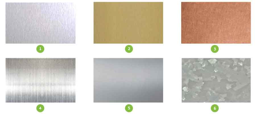
Materials
- Aluminum (1)
- Brass (2)
- Copper (3)
- Stainless Steel (4)
- Steel: CR Non-treated (5)
- Steel: CR Galvanneal and CR Galvanized (6)
Material Thickness
Because sheet metal parts are manufactured from a single sheet of metal, the part must maintain uniform wall thickness. Sheet metal thickness ranges from 0.024 in. (0.609mm) to 0.138 in. (3.505mm).
| Gauge | Steel non-RoHS | Stainless Steel | Aluminum | Copper | Brass | ||||||
|---|---|---|---|---|---|---|---|---|---|---|---|
| CRS | Galvanneal | Galvanized | 304-2B | 304 #4 | 316-2B | 5052-H32 | 6061-T6 | C101 | C110 | CDA260 | |
| 24 | 0.024 | 0.024 | 0.024 | 0.024 | 0.024 | 0.024 | |||||
| 22 | 0.03 | 0.03 | 0.03 | 0.025 | 0.025 | 0.025 | |||||
| 20 | 0.036 | 0.036 | 0.036 | 0.036 | 0.036 | 0.036 | 0.032 | 0.032 | 0.032 | 0.032 | 0.032 |
| 19 | 0.042 | 0.042 | 0.042 | 0.04 | 0.04 | ||||||
| 18 | 0.047 | 0.047 | 0.047 | 0.048 | 0.048 | 0.048 | 0.04 | 0.04 | 0.05 | 0.05 | 0.04 |
| 16 | 0.059 | 0.059 | 0.059 | 0.059 | 0.059 | 0.059 | 0.05 | 0.05 | 0.063 | 0.063 | 0.05 |
| 14 | 0.074 | 0.074 | 0.074 | 0.074 | 0.074 | 0.074 | 0.063 | 0.063 | 0.8 | 0.063 | |
| 13 | 0.089 | 0.089 | 0.089 | 0.089 | 0.089 | 0.089 | 0.09 | 0.09 | |||
| 12 | 0.104 | 0.104 | 0.104 | 0.104 | 0.104 | 0.104 | 0.08 | 0.08 | 0.08 | ||
| 11 | 0.119 | 0.119 | 0.119 | 0.119 | 0.119 | 0.119 | 0.09 | 0.09 | 0.125 | 0.125 | 0.09 |
| 10 | 0.134 | 0.134 | 0.134 | 0.134 | 0.1 | 0.1 | |||||
| 8 | 0.16 | 0.16 | 0.125 | 0.125 | 0.125 | ||||||
| 7 | 0.179 | 0.179 | 0.16 | 0.16 | |||||||
| 3 | 0.25 | 0.25 | 0.19 | 0.19 | |||||||
| 2 | 0.25 | 0.25 | |||||||||
| Gauge | Steel non-RoHS Coated Steel | Stainless Steel | Aluminum | Copper | Brass | ||||||
|---|---|---|---|---|---|---|---|---|---|---|---|
| CRS | Galvanneal | Galvanized | 304-2B | 304 #4 | 316-2B | 5052-H32 | 6061-T6 | C101 | C110 | CDA260 | |
| 24 | 0.6096 | 0.6096 | 0.6096 | 0.6096 | 0.6096 | 0.6096 | |||||
| 22 | 0.762 | 0.762 | 0.762 | 0.635 | 0.635 | 0.635 | |||||
| 20 | 0.9144 | 0.9144 | 0.9144 | 0.9144 | 0.9144 | 0.9144 | 0.8128 | 0.8128 | 0.8128 | 0.8128 | 0.8128 |
| 19 | 1.0668 | 1.0668 | 1.0668 | 1.016 | 1.016 | ||||||
| 18 | 1.1938 | 1.1938 | 1.1938 | 1.2192 | 1.2192 | 1.2192 | 1.016 | 1.016 | 1.27 | 1.27 | 1.016 |
| 16 | 1.4986 | 1.4986 | 1.4986 | 1.4986 | 1.4986 | 1.4986 | 1.27 | 1.27 | 1.6002 | 1.6002 | 1.27 |
| 14 | 1.8796 | 1.8796 | 1.8796 | 1.8796 | 1.8796 | 1.8796 | 1.6002 | 1.6002 | 2.032 | 1.6002 | |
| 13 | 2.2606 | 2.2606 | 2.2606 | 2.2606 | 2.2606 | 2.2606 | 2.286 | 2.286 | |||
| 12 | 2.6416 | 2.6416 | 2.6416 | 2.6416 | 2.6416 | 2.6416 | 2.032 | 2.032 | 2.032 | ||
| 11 | 3.0226 | 3.0226 | 3.0226 | 3.0226 | 3.0226 | 3.0226 | 2.286 | 2.286 | 3.175 | 3.175 | 2.286 |
| 10 | 3.4036 | 3.4036 | 3.4036 | 3.4036 | 3.4036 | 2.54 | 2.54 | ||||
| 8 | 4.064 | 4.064 | 3.175 | 3.175 | 3.175 | ||||||
| 7 | 4.5466 | 4.5466 | 4.064 | 4.064 | |||||||
| 3 | 6.35 | 6.35 | 4.826 | 4.826 | |||||||
| 2 | 6.35 | 6.35 | |||||||||
Because sheet metal parts are manufactured from a single sheet of metal, the part must maintain uniform wall thickness.
Sheet metal thickness ranges from 0.024 in. (0.609mm) to 0.138 in. (3.505mm).
Finishing
We offer welded assemblies, standard mill, edge breaking, and orbital-sanded surface finishes along with a number of additional sheet metal finishing options:
- Seam, tack, and stitch welding
- Hardware insertion and riveting: Standard PEM sheet metal hardware
- Powder coating: A variety of powder coat paint colors available in textured and non-textured finish, including RAL colors. View our powder coat options here
- Silk screening (one- and two-color): Colors mixed to closely match most Pantone numbers
- Assemblies: POP-riveted and welded
- Plating: Anodize, chromate, zinc, and passivate

In-house powder coating is available to streamline production, and parts are powder coated in compliance with government regulations.
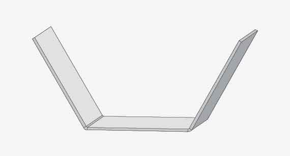
Bend Radius
We hold a +/- 1 degree tolerance on all bend angles. We offer a wide range of common bend radii, but our standard bend radius is 0.030 in (0.762mm). This is an industry standard and the most cost-effective. Flange length must be at least 4 times the material thickness.
It is recommended to use the same radii across all bends, and flange length must be at least 4 times the material thickness.
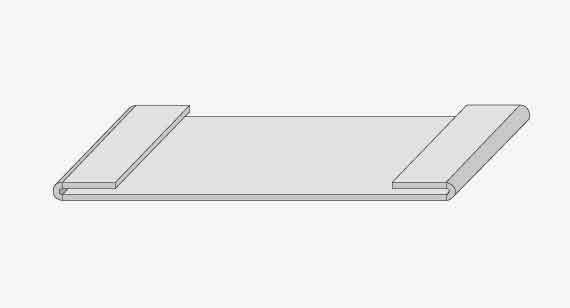
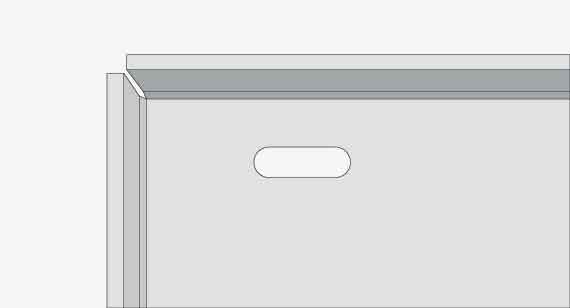
Hems
We form both open and closed hems. The tolerance of a hem is dependent upon the hem’s radius, material thickness, and features near the hem.
We recommend that the minimum inside diameter equals the material thickness, and a hem return length of 6x material thickness.
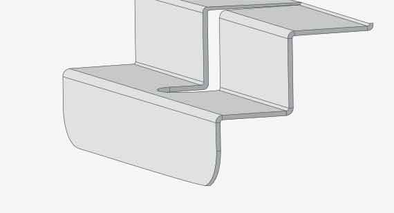
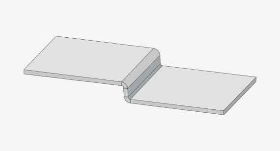
Offsets
Offsets are used to create Z-shaped profiles in sheet metal parts. We offset height tolerance at +/-0.012 in. (0.304mm) from top of sheet to top of form and recommend an offset of 0.030 in. (0.762mm).
Additional standard options include: available 0.060 in. (1.524mm), 0.093 in. (2.362mm), 0.125 in. (3.175mm), 0.187 in. (4.749mm), 0.213 in. (5.410mm), 0.250 in. (6.35mm), 0.281 in. (7.137mm), and 0.312 in. (7.924mm).
Holes and Slots
Holes and slots should be a minimum of material thickness in diameter. If a material is 0.036 in. (0.914mm) or thinner, the hole should be 0.062 in. (1.574mm) from the material edge; if the material is thicker than 0.036 in. (0.914mm), the hole should be at least 0.125 in. (3.175mm) from the material edge to avoid distortion. If hardware inserts are required, the spacing should be according to manufacturer’s specifications.
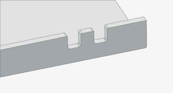
Notches and Tabs
Notches must be at least the material’s thickness or 0.04 in. (1.016mm), whichever is greater, and can be no longer than 5 times its width. Tabs must be at least 2 times the material’s thickness or 0.126 in. (3.200mm), whichever is greater, and can be no longer than 5 times its width.
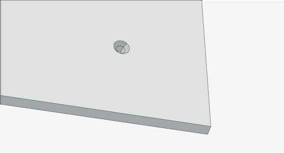
Countersinks
We offer both machined and formed countersinks—conical holes cut into a manufactured object allowing a screw, nail, or bolt to be inserted flush with the surface.
We recommend the major diameters of countersinks measure between 0.090 in. (2.286mm) and 0.500 in. (12.7mm) using one of the following standard angles: 82°, 90°, 100°, and 120°.
Tolerance for formed countersink major diameter is +/- 0.010 in. (0.254mm).

Upload a part for quote within hours
inquiry.us@made-parts.comRequest More Information
Thanks! We’ve received your message and a member of our team will be in touch with you shortly. You can find more information about China Metal Parts here:
Thanks for your interest in China Metal Parts. Please let us know how we can provide more information on our services. Once we receive your comments, an applications engineer from our team will follow-up as soon as possible.
If you have a 3D CAD model of your part ready, upload it online now to receive a quote with free design feedback.